Overscan
Techniques
This is  part one  of a  three part  article. This version has been   translated
by Frost/Sector One and has also passed the eyes of STS to smoothen it a bit. It
was originaly published in the French "ST  Magazine", issue  51 and  52   (april
-may-june  1991). The  article is written by Alien of ST Connexion (also   known
as Sengan Short / Dr Sengan  Baring  -Gould).  13 years and  one PhD later,   We
managed to  get into   contact with  him ...  in  Western  China (!). Now   that
he's back home in  Colorado,   he's revised our   translation.  The   article's
original  title  was   "Les  techniques  de l'Overscan", "Overscan Techniques".

Please note that this article was written  mainly about the ST, not the STE.  I,
Alien, had  very little  access to  STEs: I  borrowed one  for an evening, and I
tried a few things out at  the local electronics supermarket before they  kicked
me off to demonstrate it to a customer.
Part One
In this article, we  will try to explain  to you everything about  the technique
known as "Overscan". We decided to publish this article because many people  use
Overscan without  understanding how  it works:  indeed it  is necessary  to have
discovered its mechanism to know how it works. This article is the result of one
year of painstaking research, and is explained at the hardware level.

First, what is Overscan ? Also  known as "No Border Screen" or  "FullScreen", it
is a screen from which one  has removed the borders.  Before explaining  how one
performs such magic, it is useful to recall how a colour picture is displayed on
a monitor.
Picture Display
Format
A picture is displayed 50 times a second in 50Hz mode (or 60 times in 60Hz). The
ST generates 313 lines per picture at  50Hz (263 at 60Hz). In theory, it  should
generate 312.5 lines, (obtained by  successively displaying 312 and 313  lines).
It therefore assumes  the monitor can  tolerate displaying a  picture at 49,92Hz
instead of 50Hz. This also explains why the ST cannot have a real interlace mode
such as that of  the Amiga. Each line  takes a constant time  to be transmitted:
otherwise the  picture would  be distorted.  This time  is calculated  using the
following formula:

               1
-------------------------------------------------------------
(Number of pictures per second * number of lines per picture)

For "Number of pictures per second"=50 and "Number of lines per  picture"=312.5,
we get 64 microseconds. But some will wonder how come there are 313 lines, if  I
only see 200  on the screen?  The other lines  are used by  the upper and  lower
borders, and  by the  vertical synchronization  signal which  tells the  monitor
where the top of  the screen starts. Overscan  is the process of  converting the
lines used to make  up the borders into  lines able to display  a picture loaded
from memory. I will call "useable  screen" that part of the screen  not occupied
by borders.

A monochrome picture  is displayed in  the same way,  where the refresh  rate is
approximately 70Hz and each line takes 28 microseconds to be transmitted. It  is
composed of approximately 500 lines, of which 400 form the useable screen.
Video Components
Before getting into the subject, let us recall the role of each component of the
ST responsible of the display.

- The MMU: This component reads memory and sends it to the SHIFTER every 500 ns.

  Registers:
  * Address of the picture to display on next VBL:
$FFFF8201: upper byte
$FFFF8203: middle byte
$FFFF820D: lower byte (STE only)

  * Video counter, indicates the address being decoded at this instant:
$FFFF8205: upper byte
$FFFF8207: middle byte
$FFFF8209: lower byte
    Please note that you can only read from these on a plain ST, the STE however
    also allows to write to them,  which will immediately  change the  displayed
    screenarea.

- The GLUE: Produces the vertical and  horizontal synchronization signals.  It
   also produces signals telling the SHIFTER  when it should display the useable
   screen,  and  when it should show the background  colour 0  (corresponding to
   the border). It also tells the MMU when to send data to the SHIFTER.

  Registers:
  * $FFFF820A: Synchronization mode
    Bit 1 corresponds to the monitor refresh rate (0 for 60Hz, 1 for 50 Hz)

  * Resolution:
$FFFF8260  (Both the GLUE and the SHIFTER have a copy of this register)
    This byte can have  one of 3 values:  0 for low-,  1 for middle- and  2 for
    high-resolution.  The GLUE needs this register,  because in high-resolution
    the picture is displayed at ~70 Hz which requires different synchronization
    signals (see second part)

- The SHIFTER:  Decodes the data  sent by the MMU into  colour or  monochrome
   signals, corresponding to the picture in memory.

  Registers:
  * Resolution:
$FFFF8260  (Both the GLUE and the SHIFTER have a copy of this register)
    The SHIFTER needs this register because  it needs to know  how to decode the
    picture data (as 4, 2 or 1 bitplanes) and whether to send the picture out to
    the RGB pins or the monochrome pin. Indeed, if one of these pins are active,
    the other is low.  The "hardware"  proof is  that the SHIFTER  receives  the
    address bus signals A1 to A5 (no need for A0 because every address is even).
    However only A1 to A4 would be sufficient to access the palette.
Video Signals
Now we'll discuss which signals the display components use to work together.
Before diving in, a word of warning: everything said here was deduced logically
but never verified with an oscilloscope. Thus, while I'm sure of my conclusions,
I don't take any responsibility if some hardware hacker damages his ST by
trusting this article.

The MMU reads picture data from memory  and passes it on the SHIFTER, using  the
Load/Dcyc signal to  tell the SHIFTER  the data on  its data bus  comes from the
screen buffer. When this happens, the  68000 can't access the data bus.  Because
the  data  bus  is also  used  to  program the  SHIFTER  registers,  you may  be
wondering,  how  can the  68000  change resolution  or  the palette?  After  all
programs such as Spectrum 512 change the palette while the picture is displayed!
Isn't there a conflict between the 68000 and the MMU?  To help us to understand,
we notice that the 68000 has access to the address and data buses every 4 cycles
(which explains why  all instruction cycle  times are multiples  of four: a  NOP
takes 4 cycles as specified in the 68000 manual, but EXG takes 8 cycles  instead
of the 6 specified in the manual). Thus, the MMU steals the other cycles to read
the video memory and to  transfer it to the SHIFTER,  and also to deal with  DMA
Sound on the STE. On the other  hand, the MMU interrupts the 68000 for  disk-DMA
(floppy and HD)  and Blitter transfers.  Thus, if these  devices are not  turned
off, every programs  that relies on  constant execution time  (such as Overscan)
will not work correctly.
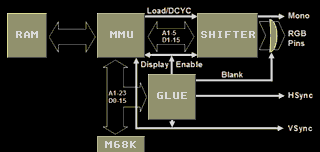
The GLUE generates the DE, Vsync, Hsync and Blank signals:

- The DE (Display Enable) signal  tells the  SHIFTER when to display the  border
  and when it has to display the  usable screen.  It also tells the MMU  when to
  send data to the SHIFTER:  It is unnecessary  to send  data and  increment the
  video counter  while the  border is  displayed.  If you cut the track  of this
  signal you will obtain a  "hardware" overscan (thanks to Aragorn who confirmed
  this by doing it). However, due to stability issues, this is  not recommended.
  The Autoswitch Overscan board (see ST Magazine 50) works in a very similar way
  by controlling this signal.

- The Blank signal forces the  RGB colour outputs to zero  just before,  during,
  and just after the Hsync and Vsync synchronization signals.  Indeed,  monitors
  require the video signal  to be 0 volts  (black colour) before  every synchro-
  nization pulse (implemented as a negative voltage): Even the border colour has
  to be eliminated to prevent overlaying the border colour over the screen while
  the electron beam returns to the beginning of the next line (from the screen's
  right to its left)  and to the next picture  (from the screen's bottom  to its
  top).  Note that the Blank signal isn't used if the screen is displaying high-
  resolution.

The Vsync and Hsync sync signals are added to the video signal:

- Vsync is the  vertical synchronization signal which specifies where the top of
  the picture is located  in the video stream.  The VBL interrupt corresponds to
  an edge of this signal.

- Hsync is the horizontal synchronization signal. It generates the HBL interrupt
  (vector $68).  The HBL interrupt  should not  to be confused  with the Timer B
  interrupt (vector $120)  which is generated  when the DE signal goes low on an
  input of the MFP:  The Timer B interrupt is triggered  only,  when the useable
  screen is displayed, because DE is inactive during upper and lower border.

The MMU uses the  Vsync signal to  reset the video counter  with the contents of
$FFFF8201 and $FFFF8203 (you may also add $FFFF820D on STE).

Knowing that  the GLUE  handles this  signals,  it  seems logical  that it would
control the process of displaying the  screen. To do this, it would  require two
counters:

- a vertical counter:   the number of currenly displayed line

- a horizontal counter: the position within the line currently being output

We will first study the vertical counter.
Top
and Bottom
Overscan
Line Counter and
GLUE
The vertical counter is  incremented every line, i.e.  at every edge of  the HBL
signal. It will be reset on each edge of the VBL.

At the top of the screen, a border will be displayed, and once a given value  of
the vertical  counter is  reached, an  internal signal  will be  set to show the
useable  screen;  let us  call  this signal  V.  V masks  the  DE signal,  which
specifies the location of the right and  left border. The V signal will also  be
deactivated when the vertical counter reaches a further value, corresponding  to
the end of the useable screen. Finally, once the counter reaches a third  value,
a VBL interrupt and the beginning of a new frame is triggered.

Based on  this, nothing  seems to  allow us  to get  rid of  the upper and lower
border. But we  must recall that  there are only  263 lines for  a 60 Hz picture
whereas there are 313 lines for a  50 Hz picture. If the upper and  lower border
had the same  height at 50Hz,  each one would  be 56 lines  high. If the useable
screen at 60Hz started  at line 56, as  it does at 50Hz,  there would only be  7
lines left for the  lower border: the useable  screen wouldn't be centered  ! On
some monitors, the bottom of the picture wouldn't even be visible...
Therefore the useable screen must start higher at 60 Hz.

At 60 Hz, the picture starts at line 34 and ends at line 234.
At 50Hz, the picture starts at line X and ends at line X+200.

Beware: the value X depends on the genation of the GLUE:
For older STs: X = 63-16 = 47 # (frost: beware also that the diagram says 49
lines).
For "newer" STs (every STs except those of ST Connexion!): X = 63.
In other words, on older STs, the picture is shifted upwards by 16 lines at 50Hz:
this explains why some obtains only 249 lines whereas others get 271 lines for a
simple Low-Border Overscan (thanks to Marlon of ST Connexion for telling me about this).

The following pseudo-code describes the work of the GLUE in a simplified fashion:

Line_Number=0
REPEAT
IF Line_Number ==  34   AND display_freq=60 THEN Activate signal V
IF Line_Number == X     AND display_freq=50 THEN Activate signal V
IF Line_Number == 234   AND display_freq=60 THEN de-activate signal V
IF Line_Number == 200+X AND display_freq=50 THEN de-activate signal V
IF Line_Number == 263   AND display_freq=60 THEN start a new VBL
IF Line_Number == 313   AND display_freq=50 THEN start a new VBL
Line_Number = Line_Number+1
END_REPEAT

Note that the frequency test happens more  than once when a new VBL is  started.
Thus, it  is not  possible to  use the  second example  program (see part #2) to
check the starting line of a 60  Hz VBL: just as well because line  263 triggers
the Low-Border Overscan on newer STs. If you want to check, make the VBL  adjust
the frequency to 50 Hz and the HBL to 60Hz at line 263.

The pseudo-code  is only  presented as  an example  to help  you understand  the
problem: the  GLUE is  not programmed  (that would  be too  slow for a component
which must  react in  500 nanoseconds).  Everything is  implemented as  hardware
logic, which explains the use of  equalities which are easier to implement  than
inequalities.
Horizontal
Overscan
Since the ST only checks whether the vertical counter is equal to a given  value
to activate or deactivate the signal V,  one can obtain a variety of effects  by
setting the refresh rate at the appropriate line.

Thus, in order to produce a Low  Border Overscan, it is sufficient to switch  to
60 Hz at the right time at the end of line 199 of the useable screen. This  will
prevent the GLUE from  deactivating the V signal:  at the value of  the vertical
counter corresponding to the  199th line of the  useable screen at 50Hz,  V will
only  be deactivated  if the  current frequency  is 50Hz.  Because the  vertical
counter is now  greater than any  of the values  that cause an  event at a  60Hz
refresh rate, there are  no other effects to  worry about. Once the  time of the
test has elapsed (the test occurs at the beginning of the line, even before  the
left border is displayed),  it is necessary to  switch back to 50  Hz, otherwise
the screen will be distorted (refer back to the pseudo-code).

It is also  possible to shrink  the screen by  switching to  60  Hz at line 234:
this  corresponds  to  the point  when the  signal V  is deactivated  at 60 Hz.
Switching back to 50 Hz,  the screen will not be  affected by the subsequent de-
activation of signal V at line X+200.

Finally, it is useful to know that  one can produce a low border Overscan  at 60
Hz: at the end of  line 199 of the useable  screen, we switch to 50  Hz and then
back to  60 Hz,  avoiding the  test  at  line 234.  We can  use the same Timer B
interrupt routine whether the  program is running at  a refresh rate of  50Hz or
60Hzin, by using the following instruction:  eor.b   #2,$ffff820a.w.  The only
commercial program that  I know that  uses this technique  is the game  "Leavin'
Teramis" by Thalion Software: during  level loading, a 22000 colours  picture is
displayed, at either 50  hz or 60 Hz  (to reduce flickering). The  green message
under the picture is displayed in the lower border in both cases.

As  the lower  overscan happens  at the  bottom of  the useable  screen, we  can
synchronize the 68000 code versus the video counter ($ffff8205 to  $ffff8209),
resulting in better stability (see next  the part for example code). It  is even
possible to use the  floppy disk DMA with  a bottom overscan. This  kind of code
trades off the  amount of time  spent at the  alternate refresh rate  versus the
amount of distortion caused on the screen.  Note that there do not appear to  be
any methods other than toggling the refresh rate to remove the lower border.

To remove the  upper border, we  simply switch to  60 Hz at  the end of  line 33
(just before line 34,  where the test happens). As the top border overscan comes
before the useable picture,  we  cannot synchronize our program using  the video
counter. Various solutions have been used:

- A stupid wait loop  from the  beginning  of the VBL  interrupt handler,  which
  wastes cpu cycles but is easy to implement. This method makes two bets:

   * First bet, the VBL interrupt will always happen immediately, which requires
     that the 68000 is not executing an instruction which takes many cycles such
     as  movem  or divu,  since the 68000 will complete its current  instruction
     before servicing the interrupt handler.

   * The Second bet belongs  to the time taken by the  GLUE before treating line
     34. It has to be a constant whichever ST is used. So far this has proven to
     be true.

- The use of a MFP timer: This method allows the more than 17000 cpu cycles
  before line 34 to be used. However this method makes the following additional
  bets:

   * Third bet, the latency to service the MFP interrupt will always be the same.
     This is true for the ST/STF series,  but some STEs that I was able to  test
     (thanks to Laurent) triggered  the interrupt 60 cycles later than on a STF!
     The bottom overscan of Leavin' Teramis doesn't' work on those STEs, even if
     the program  detects the STE:  This  shows that this delay varies according
     to your model of STE.

   * Fourth bet, unless we leave some dead time during line 34, we may encounter
     the same problem for the MFP interrupt as described in the first bet!

- The use of the HBL interrupt: this interrupt is nearly never used on the ST,
  and is even forbidden by the ROM (its interrupt handler, pointed to by vector
  $68 has as only function to mask this interrupt). As this interrupt is
  triggered by the Hsync signal, it occurs on every line (including borders and
  the useable screen), which makes it perfect for counting lines up to the 34th
  line after the VBL. But it has a drawback, which explains why this method is
  rarely used:  The HBL  interrupt occurs at the  beginning of the line, and the
  68000  takes at least  44 cycles  to enter the  interrupt handler, so that the
  interrupt  handling routine  is executed  in the middle of the  left border...
  Which is ugly if one uses it to change the palette!
  To remove  the upper  border,  each  HBL interrupt  will check  whether it has
  reached line 33. If so, it will wait (with a DBF and some NOPs)  until the end
  of the line to toggle the refresh rate. This way, we lose lose less cpu time
  than the first method, and we don't depend on the MFP.

  This method takes 2 bets:

  * First bet, the number of HBL lines to count will not change, whatever the ST
    we use:  This has never happened, and if it ever would,  none of other means
    of  removing  the upper border,  described above,  would work.  However this
    method will survive when the previous methods will not: The time between the
    VBL and line 34 may vary by up to a quarter of a line without  affecting the
    number of HBLs that must be counted...

  * Second bet, the time taken to service  the HBL interrupt will be a constant.
    Again,  I have never  seen this not to be true,  and it is hard  to see why
    Atari  would add  extra  circuitry to  this signal:  Some  chips  were added
    between the MFP and the 68000 on the STE,  but the MFP is fully used by this
    computer. Atari's disdain for the HBL should preserve its reliability.

It is  impossible to trigger a top  overscan in 60 Hz using a 50/60 Hz frequency
switch.

There is another method of removing the upper border: one switches to monochrome
output at the beginning of the VBL. This technique allows us to use most of  the
34 lines  above the  top border  overscan described  above. Unfortunately,  this
method only works on some STs, but not on STEs... This method relies on the fact
that a monochrome screen has an  even shorter top border since the  refresh rate
is 70Hz.  By switching  back to  50 or  60 Hz,  after the  video counter  starts
incrementing, one obtains a top border overscan. However, I've noticed that  one
does not remove  the upper border  if one switches  back to 50/60Hz  immediately
after the video  counter starts. Instead  one is able  to synchronize the  68000
with the  video counter  allowing one  to change  the colour  of the border at a
precise location, like BMT seems to do in the third screen of the Skid Row  demo
(see ST Mag 47, page 14). As  this technique is not reliable, I don't  recommend
it, to prevent  certain people from  complaining... (This is  an allusion to  an
article  previously  published  in  ST  Magazine,  written  by  Belzebub  of  ST
-Connexion, complaining that most overscans do not work on his ancient ST).

Now that we have learnt how to remove the upper and lower borders, it should  be
easy to  remove both  in the  same screen.  But a  subtlety is often forgotten !
Without top border overscan, we can use Timer B interrupt to trigger the  bottom
overscan, so the border is removed whatever value of X, the number of the  first
line of the useable screen. We  cannot use the same technique when  removing the
upper border: to remove the lower border, we must toggle the refresh rate twice,
with an interval of  16 lines. This will  guarantee compatability with the  most
recent STs as well as antiquities.

This is the end of the first  part of the article about Overscan. The  next part
is about creating left and right border overscan and about the internals of  the
SHIFTER.  We'll learn  about shifting  the useable  screen around,  the need  to
stabilise left/right overscan and  how to reset the  SHIFTER. The third part  is
about fullscreen overcan, hardscroll and extended palettes.

We hope that this series of articles prejudice anyone. Its purpose is to correct
the imbalance between those that have contacts, access to source code, or access
to cracked  demos, and  those that  do not.  It will  demystify Overscan,  often
considered a magic recipe, and a landmark of programming progress. In this way I
hope we'll  see fewer  boring copycat demos, like mega-scrollers.  Overscan  and
Hardscroll  deserve  more  respect,  as  those  that  discovered  them  know how
difficult it is to find them.  I therefore hope to see more Fullscreens that are
worth keeping.

Sengan SHORT (Alien of ST Connexion)

Rough translation by frost of Sector One (http://deunstg.free.fr/sct1/)
Translation revised by Alien of ST Connexion 2005. (www.electronincantation.org)

Believe it  or not,  ST Magazine  still kind  of exists  (http://stmagazine.org)
which  is  pretty  cool,  since  at the  time  it  beat  all  other European  ST
publications, and was probably critical in  the rise of French Demo Groups  from
1991 onwards (http://wwwbrauer.in.tum.de/~brandtf/ataridemos.html). You may also
know the archive that contains most of the scanned issues of the old ST Magazine
at (http://www.microstalgia.fr.st/).
|