Overscan
Techniques
Part II
        Stabiliser

        So now we know how to remove the left border, and we know how to
        remove the right border, shouldn't removing both lead to
        overscan? This is where my research was stuck for 3 months...
        The problem is that one obtains an unstable overscan. This was
        predictable as we learnt above that lines in left overscan start
        500ns earlier, and the example of right overscan at 60Hz taught
        us that right overscan is unstable if it starts 500ns earlier.
        The instable right overscan displayed the useable screen 8
        pixels early every second line, which is exactly what one
        observes if one removes both borders! The only difference is
        that the lines have lengths of 226 or 234 bytes, i.e. 230 +/- 4
        bytes. One recognises the word too many that is swallowed by the
        opening of the left border: 226 = 224 + 2, where 224 is a
        multiple of 8; and 234 = 232 + 2 where 232 is a multiple of 8.
        In fact the MMU reads 230 bytes each line, but the SHIFTER
        displays 226 (less the 2 it ignores) or 234 (-2). This shift
        doesn't seem all that bothersome at first glance since one could
        shift the contents of every second line by 8 pixels. However if
        one wants a partial overscan (removing the borders only on some
        lines), the remainder of the normal useable screen will also be
        shifted left if it starts on a shifted line. Furthermore, the
        shift is perpetuated from VBL to VBL, so that at each new VBL
        two words are introduced. Thus the useable screen trembles, each
        line being shifted differently every VBL.

        Some STs have a combination of MMU, GLUE and SHIFTER chips that
        allow them to tollerate such an overscan if an even number of
        lines have their borders removed. Others don't because the DE
        signal is sometimes activated, sometimes disactivated at the end
        of each line, the GLUE and the SHIFTER being out of synch. One
        remedies this situation by using a stabiliser, of which there
        are different kinds. Stabilisers exploit the internal state of
        the SHIFTER to make it believe that it is dealing with a
        multiple of 4 words length line. To do this one changes
        resolution during the useable screen. We saw that changing
        resolution immediately changed the way the SHIFTER decodes
        bitplanes. In fact it also changes the way it manages its IR
        registers. Thus a stabiliser could be implemented by a
        transition to medium resolution. But since each stabiliser
        functions differently, we will only study one: transitioning to
        high resolution at position 108. This is the stablest
        stabiliser. In fact this transition could occur at any position
        that is a multiple of 4 because at these positions the internal
        state of the RR and IR regiters is the same. The position 108 is
        chosen because it is on the extreme right of the picture, hiding
        the effect of the stabiliser. Indeed this stabiliser causes 12
        black pixels followed by 16 pixels with displaced bitplanes to
        be displayed. The 12 pixels correspond to the 12 cycle
        transition to high resolution.
At position 108, a secondary effect occurs: the Blank signal is
activated 2us later on an STF, causing 16 pixels to be displayed
further right that is usually possible.
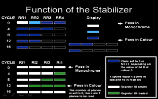
The stabiliser thus consists of transitioning to high resolution
for 12 cycles, followed by a return to low or medium resolution.
The transition occurs just before the RR registers are loaded
with the contents of the IR registers (Recall that the 68000 and
the SHIFTER are out of sync so that the MMU can send image data
to the SHIFTER while the 68000 changes the palette). During the
first 12 cycles the RR registers act as they would in high
resolution. The switch back to low or medium resolution occurs
just before RR1 is loaded with the contents of RR2, RR2 with
that of RR3 (and so on). Thus RR3 and RR4 contain after these 12
cycles $0000 or $FFFF according to the value of bit 0 of colour
0 (BE). RR2 contains what was in RR4, and RR1 contains what what
was in RR3.
There are then 4 pixels to show that will be shown in the wrong
colours: colours 0-3 or 12-15 depending on whether RR3 and RR4
contain $0000 or $FFFF (RR1 corresponds to the least significant
bit of the colour, while RR4 corresponds to the most significant
bit of the colour: see "La Bible ST" chapter 3.4).
Now consider the IR registers: when the switch to low or medium
resolution occurs, IR4 has yet to be loaded, but the switch at
this position has as effect to force Number_of_read_bitplanes to
4. Since the RR registers are not yet empty, the SHIFTER does
not reinitialise them, but starts to reload the IR registers.
There are now still four words to read until the end of the
line, so the next line will not be shifted. Notice that for 4
cycles after the return to low or medium resolution, the SHIFTER
continues to rotate the RR registers as if it were still in high
resolution. Thus at that time, RR2 to RR4 contain $0000 or
$FFFF, while only RR1 comes from screen memory: RR1 contains
what was in RR2 four cycles before, and therefore what should
have been displayed in RR4. Its colours correspond to the colour
0-1 or 14-15 of the palette, respectively. A stabiliser
consisting of a switch to medium instead of high resolution at
this position also works, but the screen is sometimes shifted by
a pixel horizontally. This occurs seemingly randomly.
Resetting the Shifter
Exiting certain overscans often causes the bitplanes of the
following normal screen to be displaced. This occurs because the
last line of the overscan was missing its stabiliser. While in
overscan, one doesn't observe the displacement of bitplanes
because the stabiliser of the first line of the next VBL clears
the effect. Sometimes they hide the effect further by setting
the colours to zero during that first line. To restore the
picture at the end of one of these programs. one must reset the
SHIFTER. This is done by using a sequence of switches of
resolution at the begining of each VBL during the border, while
DE is disactivated. It has the effect of clearing out the
registers of the SHIFTER. I recommend that you use the timings
indicated in my example programs so that your demos work on
every ST. Finally do not "optimize" your code by removing the
stabiliser, which MUST ALSO BE PRECISELY PLACED. This would
returning to the state of the art 3 years ago!
In our next episode, a full overscan program will be given
including its possible variations. Hardscroll on the STF will
also be explained, illustrated with source code. Finally another
SHIFTER effect will be described: how to extend the palette to
24389 colours...
|