Overscan
Techniques
Part II
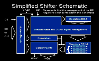
        The internal structure of the SHIFTER:

        As the GLUE controls the DE signal, one would expect the
        beginning of the useable screen to always occur at the same
        location on the screen. However, if one removes the right
        border, one will see that the useable screen starts slightly
        further to the left than it does in the normal non-overscan
        mode. The SHIFTER is responsable for this effect. Unlike the
        GLUE, it is a complex circuit. Providing a full explanation of
        its function is beyond the scope of this article. Instead I
        present here a simplified explanation, which may describe
        certain aspects poorly, but suffices for this study.
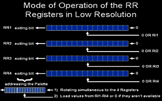
        The SHIFTER contains 4 16-bit registers RR1 to RR4, where RR
        denotes Rotating Register. Each of these registers undergoes a
        continuous rotation, shifting out their most significant bit on
        each rotation. The most significant bits thus output are used to
        address colours in the palette which is directly linked to the
        RGB pins. For instance in low resolution, the four RR registers
        are shifted so 4 bits are output at a time, corresponding to the
        4 bitplanes. Thus, after 16 rotations, RR1 to RR4 are "empty".

        The four RR registers are updated simultaneously and at the same
        time, whatever the resolution. Consider medium resolution. It
        only uses 2 bitplanes, so only two registers RR1 and RR2 are
        being shifted. It doubles the horizontal resolution (640
        pixels), so both registers are rotating twice as fast as in low
        resolution. Each time the RR registers are shifted, their least
        significant bit is cleared. Once RR1 and RR2 have been
        "emptied", they are updated with the contents of RR3 and RR4,
        which are themselves emptied.

        High resolution is processed slightly differently: only RR1
        rotates, but at four times the speed it does in low resolution.
        The exiting bit addresses bit 0 of colour 0 in the palette to
        determine whether the picture should be shown in inversed video.
        It is also reinserted as the entering bit of RR1, so RR1 is
        rotated rather than shifted. When RR1 has been emptied, it is
        updated with the value of RR2; RR2 is updated with the value of
        RR3 and RR4 with that of RR3. RR4 is then empty, and is filled
        with $0000 or $FFFF depending on the value of bit 0 of colour 0.

        The SHIFTER also contains four temporary bitplane registers: IR1
        to IR4, where IR denotes Internal Register. Their behaviour is
        given by the following pseudo-code:

Number_of_read_bitplanes = 0
REPEAT
 IF Load is active THEN IR[Number_of_read_bitplanes] = Data sent from MMU
                        Number_of_read_bitplanes = Number_of_read_bitplanes + 1
 IF Number_of_read_bitplanes == 4 AND IF DE is active
    THEN RR1 = IR1; RR2 = IR2; RR3 = IR3; RR4 = IR4
 IF Number_of_read_bitplanes == 4 THEN Number_of_read_bitplanes = 0
END_REPEAT

        This process is continuous, and depends in no way on the
        synchronisation signals sent by the GLUE. Thus the RR registers
        are only reset when four bitplanes were received. As the RR
        registers are permanently rotated, they are emptied when the MMU
        sends no data or when DE (Display Enable) is off. In low and
        medium resolutions, each shift fills the least significant bit
        with a zero, which explains why the border colour is determined
        by colour zero in the palette. In high resolution they are
        filled by the value of bit 0 of colour 0 (signal BE)
        guaranteeing that the border is always black. This avoids the
        use of the Blank signal when the monitor's electron gun returns
        to the next line. This can be verified by causing the SHIFTER to
        display something during this time: it is displayed as a
        diagonal trace on the screen (it is extended and grey rather
        than white as the electron beam is moving quickly).

        Note that every change of resolution immediately changes the
        SHIFTER's behaviour: RR1 to RR4 will be treated differently, and
        any momentary switch to high resolution will appear as a black
        line on a colour monitor and a horizontal line on the monochrome
        monitor. This corresponds to a temporary disactivation of the
        RGB pins and the activation of the Mono pin. If transition
        occurs during the useable screen, the effect obtained differs on
        STF's and STE's, and differs according to the exact position on
        the screen in which it occured. For instance, there is a
        position from which a black line will extend all the way to the
        extreme right of the screen. This corresponds to the activation
        of the BLANK signal by the GLUE. These effects do not change the
        way in which the screen is decoded, or the synchronisation
        signals are generated.
|