Overscan
Techniques
Part II
Welcome back to our study of the Atari ST's video circuits, as
illustrated by Overscan. Last episode described the interactions
between the three chips that are involved in displaying the
screen (The MMU, the GLUE and the SHIFTER). It also described
the methods used to remove the top and bottom borders. We
continue in this article with...
Left and Right overscan
The horizontal counter is incremented every 500ns (aka every
0.5us). It is reset every HBL. Thus the MMU sends a word to the
SHIFTER every 0.5us . Notice that at 50Hz a line will last 64us
while at 60Hz it will last 63.5us. Also note that the SECAM
specification requires that the horizontal synchronisation pulse
should last 0.47us. However because the GLUE only has a
resolution of 0.5us, the ST relies on the tolerance of the
monitor and emits an Hsync signal of 0.5us.
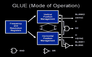
The GLUE goes through a similar process to display each line as
it does to display the whole picture: first a border. This is
achieved using a signal H (as in Horizontal) which is active
during the portion of the line to be displayed. H and V are
combined using an AND gate to give the signal DE (Display
Enable). Thus only when H and V are active, is a useable screen
displayed.
H is activated once the horizontal counter reaches a first value
at the end of the border. H is deactivated once the horizontal
counter reaches a second value at the end of the useable screen,
40us later. Finally once the horizontal counter reaches a third
value, the Hsync signal is activated for 500ns and a new line is
started. Notice that while these three values depend on the
display frequency, the length of a standard useable line is
always 40us (that is to say 160 bytes output every 0.5us as
words).
The following pseudo-code describes the GLUE's work. Note that I
did not determine the exact moment the HBL interrupt takes
place, and therefore a constant should be added to the following
numbers. Similarly, there is little value in determining Y.
Position=0
REPEAT
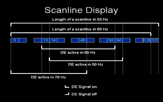
IF Position == 13 AND display_freq=60 THEN Activate signal H
IF Position == 14 AND display_freq=50 THEN Activate signal H
IF Position == 93 AND display_freq=60 THEN Disactivate signal H
IF Position == 94 AND display_freq=50 THEN Disactivate signal H
IF Position == Y AND display_freq=60 THEN Activate signal Hsync
IF Position == Y+1 AND display_freq=60 THEN Disactivate signal Hsync
and start a new line
IF Position == Y+1 AND display_freq=50 THEN Activate signal Hsync
IF Position == Y+2 AND display_freq=50 THEN Disactivate signal Hsync
and start a new line
Position = Position+1
END_REPEAT
Based on this we can obtain different overscan effects, as was
done in the previous article:
* Right Overscan by switching to 60Hz at position 94, overiding
the 50Hz end-of-useable-line detection, and then returning to
50Hz. Each line is now 160 + 44 = 204 bytes long. At 50Hz this
mode is stable on all ST's. Notice that 204 bytes is not a
multiple of 8, and therefore 2 bitplanes on the extreme right of
the picture are not displayed.
It is important to return immediately to 50Hz, otherwise STE's
react bizzarely and distort the screen.
At 60Hz, right overscan is also possible by playing the same
trick at position 93. The length of each line is still 204, but
the line must be stabilised (the principle of stabilisation is
described below). Furthermore I have not checked whether this
kind of line can be stabilised on all STs.
* 158 byte line at 50Hz by switching to 60Hz at position 93,
enabling the 60Hz end of line detection. The line is shorter by
a word, corresponding to the difference of 0.5us between the two
times to display a line (63.5us versus 64us).
* 0 Byte line by switching to 60Hz at position 14 (detection of
the beginning of a line at 50Hz). This method is not recomended,
because it doesn't work once out of every twenty times the ST is
powered on. This happens when the timing of the GLUE and the MMU
are offset in such a manner that the 68000 cannot access the bus
on the precise cycle required to change the frequency. Recall
that it is the MMU that decides which of every four cycles will
be allocated to the 68000, and that at on power on circuits can
receive parasitic noise on the clock signal that could
potentially cause this offset.
Thus we have obtained a right overscan, but have no clue as to
how to remove the left border. It is obvious that the GLUE
pseudo-code given so far cannot help us in any way. Therefore we
need to look at the other available register settings. As we
discouraged any use of external synchronisation, all that is
left is switching to high resolution mode. The structure of the
screen is very different in hires than that we have looked at so
far: each line contains only 80 bytes instead of 160, and each
line only takes 28us (20us for the useable screen, and 8us for
the border and Hsync) instead of 64us. Thus each monochrome line
will have a smaller left border so that the useable line will
start earlier, and as it only contains 80 bytes it will also
finish earlier. Thus we need to add the following lines to our
GLUE pseudo-code:
IF Position == 0 AND display_freq=70 THEN Activate signal H
IF Position == 40 AND display_freq=70 THEN Disactivate signal H
IF Position == Z AND display_freq=70 THEN Activate signal Hsync
IF Position == Z+1 AND display_freq=70 THEN Disactivate signal Hsync
and start a new line
(Determining Z is of no value)
It is therefore sufficient to switch to monochrome to activate H
and DE, and therefore force the MMU and the SHIFTER to start
decoding the useable screen. One returns to low or medium
resolution to actually see the useable screen on the RGB pins.
Thus one obtains at 50Hz lines of 160+26 = 186 bytes. At 60Hz
one obtains lines of 184 bytes. The difference of 2 bytes
corresponds to the difference of 0.5us between the two line
lengths (63.5us at 60Hz and 64us at 50Hz).
        Furthermore if one switches to monochrome at position 40, one
        obtains line lenght of 80 bytes (if the left border has been
        removed) or of 80-26 = 54 bytes (not removing the left border)
        corresponding to the 80 bytes of each high resolution line. Note
        that one has to quickly return to low or medium resolution to
        avoid causing an Hsync and a new line.

        Note that one can obtain remove the right border by switching to
        monochrome at position 94 at 50Hz (overiding the end-of-useable-
        line detection) but that this method causes a black line to be
        displayed between the normal screen and the right overscan (see
        explanation below). A 0 byte line can also be obtained. This
        method is stable but because it occurs at the time Hsync is
        being processed, it can distort the screen.
|